Logiciels
> Proteus
> EasyHDL
generator > RC5 code
Last update : 03/11/2009Version franšaise
Overview
This little article show how produce a RC5 frame as those used with IR (InfraRed) remote control, with the EasyHDL generator included into Isis. To allow testing the generated RC5 code, an Isis design is provided, that make usage of a PIC 16F628A running *.hex file that has been written and compiled under MikroPascal Pro. On the PIC is connected a LCD display that show decoded RC5 code, and some pins of the PIC are activated on reception of some specific RC5 codes.RC5 code overview
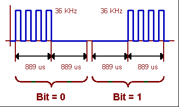
This article talk about the production of a RC5 frame on logical level, not on the bi-phase modulation level (Manchester code) of the infrared light at a 36 KHz (or other freq) carrier. Just say that the low logical level (0) is corresponding to an IR beam modulation during 889 us, followed by no modulation at all during the same time. And that the high logical level (1) is corresponding to a "silence" of 889 us, followed by an IR beam modulation during the same time.
36 KHz scale volontary not respected
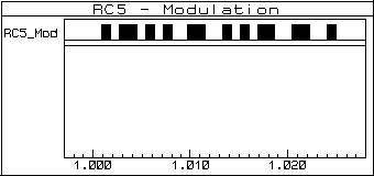
Viewed from far distance, we have a pulses suite, with activity and silence that depend on bits to transmit.

Frame with adresse = $05 and command = $35
RC5 frame is composed by 14 bits :
- 2 Start bits always set to 1 (only one Start bit for extended RC5 code)
- 1 Toggle bit, which state change when the tx key is released and again pressed (used for continuous tx detection)
- 5 bits for address number
- 6 bits for command number (7 bits for extended RC5 code)
Code sample
We'll now see how to generate a single RC5 frame, to make easier its
decoding simulation and testing. This frame is made with a header that
it is not necessary to change for our purpose : let the 2 Start bits to
"1" and the Toggle bit to "0".
Follow the 5 bits used for address number and the 6 bits used for the
command number. Of course, we can use the easiest way to generate a
single RC5 frame : change manually bit to "0" or "1", depending on data
to transmit (it was what I made on begining), as the following
(incomplete) code idea show it :// RC5 "simple" code generator
// header, bits #1 and #2
SENDBIT1
SENDBIT1
// toggle bit, bit #3SENDBIT0
// address, bit #4 to bit #8
SENDBIT0
SENDBIT0
SENDBIT1
SENDBIT0
SENDBIT1
// command, bit #9 to bit #14
SENDBIT1
SENDBIT1
SENDBIT0
SENDBIT1
SENDBIT0
SENDBIT1
But doing that this manner, it is not really easy to change address or command values : it's prone to errors and time consumming. So I decided to write some lines of code to allow specify address and command values in simple byte variables. EasyHDL code extract needed bits of these two variables and ignore the others, and only start and end frame are hard coded. Following sample generate a RC5 frame where address = $05 and command = $35.
// RC5 code generator
// 1 - Define data to be output
// not include the two start bits// only include Address and Command values
DATA 0x05,0x35
// 2 - Define IR speed
FLOAT BITTIME=1.778m
FLOAT BITTOGGLE = BITTIME / 2
// 3 - Declare working variables
INT DataOut
INT i,j,d,dTmp
// 4 - Top level
OUT = 0
SLEEP FOR 1000m // start after delay of 1 sec
// send header and toggle now, bits #1 to #3
GOSUB SENDBIT1
GOSUB SENDBIT1
GOSUB SENDBIT0
// address, bit #4 to bit #8// -> handled in following sub-routine when i=1
// command, bit #9 to bit #14
// -> handled in following sub-routine when i=2
// 5 - Read Data to send
LOOP:
i = i + 1 // i=1 > Address, i=2 > Command
if i > 2 THEN GOSUB THEEND
READ d
GOSUB OUTDATA
GOTO LOOP
// 6 - Send Data
OUTDATA:
// Data bits
FOR j=0 TO 7// i=1 > Address, read only bits #3 to #7
IF i=1 THEN
IF j < 3 THEN
CONTINUE
ENDIF
ENDIF
// i=2 > Command, read only bits #2 to #7
IF i=2 THEN
IF j < 2 THEN
CONTINUE
ENDIF
ENDIF
IF (d & (1 << 7-j)) THEN
GOSUB SENDBIT1
ELSE
GOSUB SENDBIT0
ENDIF
NEXT j
RETURN
SENDBIT0:
OUT = 1
SLEEP FOR BITTOGGLE
OUT = 0
SLEEP FOR BITTOGGLE
RETURN
SENDBIT1:
OUT = 0
SLEEP FOR BITTOGGLE
OUT = 1
SLEEP FOR BITTOGGLE
RETURN
THEEND:
// end of Tx
OUT = 0
END
1 - Define data to be output
We define here the data to send, with the DATA keyword, that is followed by the two bytes to transmit (even if 8 bits are not all used, as this will be seen later). As data to transmit are hexadecimal values coded on 8 bits, we write them byte after byte, with "0x" suffix. The following lineDATA 0x05,0x35
indicate that we have to transmit the two bytes $05 et $35, one after the other.
In our case, RC5 frame start with 3 bits that are always the same (1-1-0) , no need to define them at the moment, they will be hard coded latter. Here, only Address ($05) and Commande ($35) have to be specified. In this manner, modifying Address or Command value is not really difficult...
2 - Define IR speed
We define here a FLOAT constant value that store the time that ellapse between each bit of the RC5 frame, that of course depend on the speed transmission. Here, this time is 1.778 ms, that is equivalent to 64 periods of a 36 KHz carrier.3 - Declare working variables
Just define here some variables that are used latter.4 - Top level
Point where signal generator start to really send some data's.5 - Read Data to send
At this place, a loop read each data line that has been specified at begining of the EasyHDL code with DATA keyword. On the first pass of the loop, first element (byte) of the first DATA line is read and put into a variable with the READ keyword.The first DATA line, that contain two values to handle :
DATA 0x05,0x35
is then read in two successive steps, with the line
READ d
that see that there are two values to handle, these two values are separated by a comma.
The first value "0x05" is copied in the d variable, and the sub-routine OUTDATA is executed to work with this value. Once work is finished with this value, the second value "0x35" is copied in the d variable and the sub-routine OUTDATA is again executed to work with this new value. The i variable is incremented at each loop pass, and is used for the next operations : if i variable has the value "1", then the bit quantity to work with in this byte will be limited to 5 (byte containing address value); if i vairable has the value "2", then the bit quantity to work with in this byte will be limited to 6 (byte containing the command value).
6 - Send Data
That's here that the biggest work is done. Each byte is decomposed bit to bit, all bits are transmitted one after the others, on a length that depend of the byte "type" : if this byte contain Address value (i variable = 1), we only read the last 5 bits; if the byte contain Command value (i variable = 2), we only read the last 6 bits.SENDBIT0 et SENDBIT1
Simply two sub-routines that avoid to repeat the same thing at different places of the EasyHDL code.Sample application in Proteus / Isis
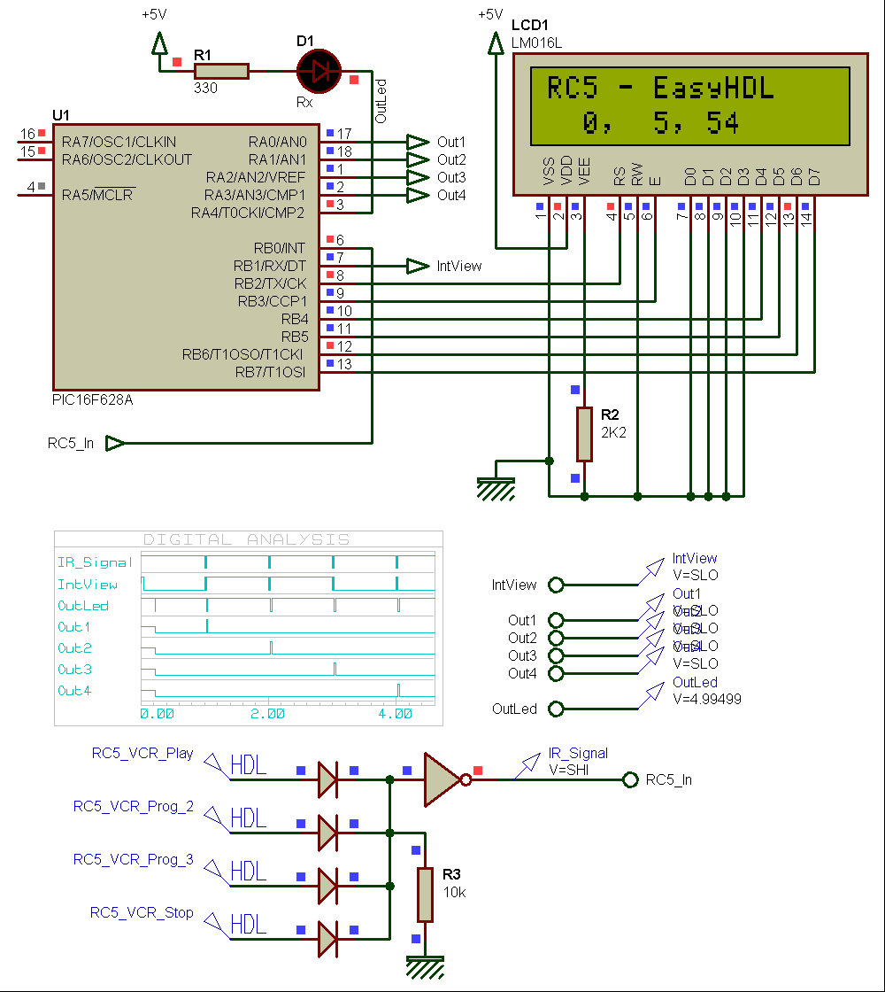
The previous EasyHDL code have been tested in following Proteus / Isis design.
The LCD display show on the second line - in decimal - the value of the Toggle bit (always 0 in our case), the Address value (5 on schematic) and the Commande value (54d for $35).
Remarques
- Data incoming on RBO input are in "inverted logic" : on iddle time, this line has a high logic level.
- Schematic integrate 4 EasyHDL generators for transmitting 4 different frames at different moments, but of course it is possible to generate the four frames in only one EasyHDL generator.
Proteus - EasyHDL - RC5 - Isis design and PIC compiled software