
Logiciels
> Proteus
> Simulation in ISIS and packages in Ares
Last update : 11/05/2009Version franšaise
Overview
Isis integrate large components libraries, associated for more of them with simulation model and/or physical footprint (package). We can do a quick selection for all of them :- schematic components without simulation model and without package (for example Z80).
- schematic components with simulation model and without package (for example RELAY ou BUTTON).
- schematic components without simulation model and with package (for example CD4541).
- schematic components without simulation model and without package (for example 16F628A)
Some of Isis components are mainly integrated to allow "pure" simulation, with no PCB construction intention. It's the case for example with the push button (BUTTON), mechanical BCD encoder (THUMBSWITCH-BCD) or basic relay (RELAY). These components are easy to find as they have no number reported on their terminal connections, supposing they aren't classified in basis components as resistor, capacitor, diode or transistor (that have hidden connection numbers). What I want to talk here is how to add a physical footprint definition in a "pure simulation" component. For this, I'll use an example that can be easyly transposed for other components, and that is focused on the seven segments display with common cathodes 7SEG-COM-CATHODE component.
7SEG-COM-CATHODE component
The 7SEG-COM-CATHODE component allow to display a number comprised in the range 0..9, with red color segments (color is not important for us). It has many connection terminals that allow accessing to common point and to individual segment. On the following schematic, only one component has numbered connexions (it's U1), others have no number on their pins.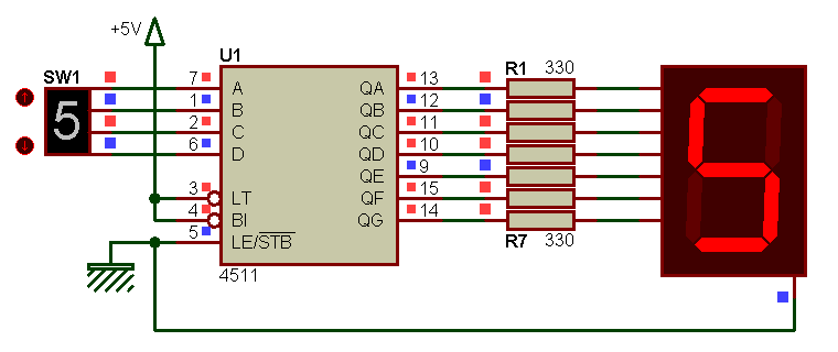
For resistors, it is normal, no need to saturate schematic, that is enough readable as this. For seven seg display, it is normal too, as it was designed as a "pure" simulation" part. Now, suppose that we want make a PCB that support BCD decoder (U1), R1 to R7 resistors and a real seven seg display as the D350PK one. When transfering netlist from Isis to Ares, there is no trace of the display in the Ares "to place component list", even we made effort to uncheck the "Exclude from PCB Layout" option of this component in Isis. And Ares ask us a footprint for it, that is natural. You already specified a footprint with numbered pins for the display that already exist in your library, but Ares is not OK and complain that pins of the Isis display have non number matching actual pins ? Another time, it is normal, as display model doesn't have numbered pins.
Solution N░ 1
Using actual (not modified) Isis component is possible, if the specified footprint have pins labeled as pins in Isis component, ie with letters or word and not with numbers. 7SEG-COM-CATHODE component from Isis library has 8 pins : 7 pins por individual segments ("A" Ó "G") and 1 pin for common connection ("COM"). Corresponding footprint for D350PK physical display can be drawn as following, with two additionnal pins, as real part have two common pins and one DP (Decimal Point) pin, that are not showed in Isis part :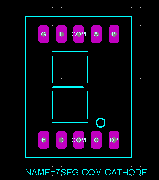
Once footprint is created in Ares with pins labeled by letters, you can specify it in Isis trough the PACKAGE property that tell Isis what physical part have to be associated with schematic component. Here, name of the footprint in Ares is the same as name of component in Isis, but it can be different :
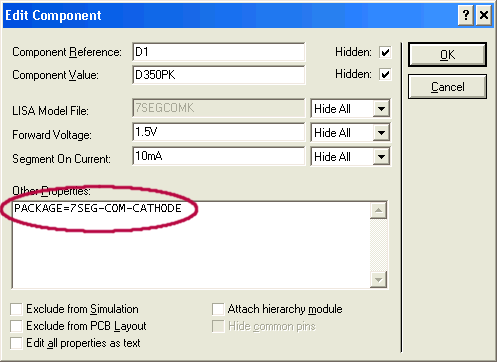
This works well as this, and produced netlist in Isis is well accepted by Ares, that allow immediatly to place the display part, with corresponding ratsnet. Routing can be started.
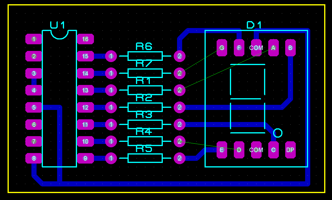
One little regret : after routing one of the two common ("COM") pin, Ares is happy for the link and don't show anymore that other "COM" pin has to be connected. It's right, Isis has only one "COM" pin...
Advantages
- Quick to do, we have just to create a package footprint in Ares, that have pins with same names that the Isis component.Disadvantages
- Using footprint that have several pins with the same name can cause problems (no raise of connectivity error if at least one is routed).- Letters can be less "talking" than numbers, for orientation as example.
Solution N░ 2
A second method (that I prefer to work with) can be used : using a footprint with numbered pins. In this case, Isis component must have numbered pins. And as our previously used 7SEG-COM-CATHODE display have no number, we have to add them. At this step, we can edit existing part and save modifiations in the same component, or create a new component based on the existing one and using the same simulation model. That's how we'll do here, and it's really easy and quick to do. For this we'll do the following :- place a 7SEG-COM-CATHODE component in Isis main sheet, and decompose it.
- give a number at each actual pins, and add the two missing pins (second "COM" pin and "DP" pin).
- compile all this in a new component, arbitrary called D350PK.
At the end, we'll get in Isis library a new component called D350PK that we'll share the same simulation model than 7SEG-COM-CATHODE component, and at wich a physical footprint will be attributed (here, I have choosen the same name for Isis new component and for footprint, but they can be different).
Placing and decmposing 7SEG-COM-CATHODE component
Once 7SEG-COM-CATHODE component is placed on the Isis sheet and decomposed, display the properties editor of the component, to see actual properties and associated values. After that, search for and modify following lines, as indicated :- modify NAME property from DEVICE group : old value = 7SEG-COM-CATHODE, new value = D350PK
- modify PACKAGE property from PROPDEFS group : old value = PCB Package,HIDDEN PACKAGE, new value = "PCB Package",PACKAGE,1,D350PK
- modify PACKAGE property from COMPONENT group : old value = NULL, new value = D350PK.
- add PREFIX property with a value of "D" (D comme Display), so Isis will be capable to add a prefix identifier when placing component on the worksheet (D1, D2, etc). If you don't want prefix be the same as diodes prefix, choose another one.
To summarize :
Before modifiation
{*DEVICE}
NAME=7SEG-COM-CATHODE
{*PROPDEFS}
{PACKAGE=PCB Package,HIDDEN PACKAGE}
{*COMPONENT}
{PACKAGE=NULL}
(other lines are ignored for beter reading, don't touch them)
After modification
{*DEVICE}
NAME=D350PK
{PREFIX=D}
{*PROPDEFS}
{PACKAGE="PCB Package",PACKAGE,1,D350PK}
{*COMPONENT}
{PACKAGE=D350PK}
Specify number to actual pins, and add missing pins
- Specify number 7 for "A" led segment, specify number 6 for "B" led segment, etc, according D350PK pinouts.- Specify number 3 to existing "COM".
- Add a pin labelled "COM2" and specify it number 8 (second COM wire of the real display).
- Add a pin labelled "DP" and specify it number 5 (DP = Decimal Point).
Compile modified component in a new "D350PK" component
Select component with its text properties, and call the Make device command (Library menu) to create a new component. Specify all required values in successive tabs of the create new component window, and save component in the library of your choice. And it's done ! Now you have a ready to use component that can be simulated and that have package.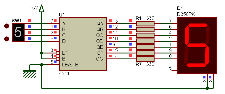
Of course, specified package must already exist !
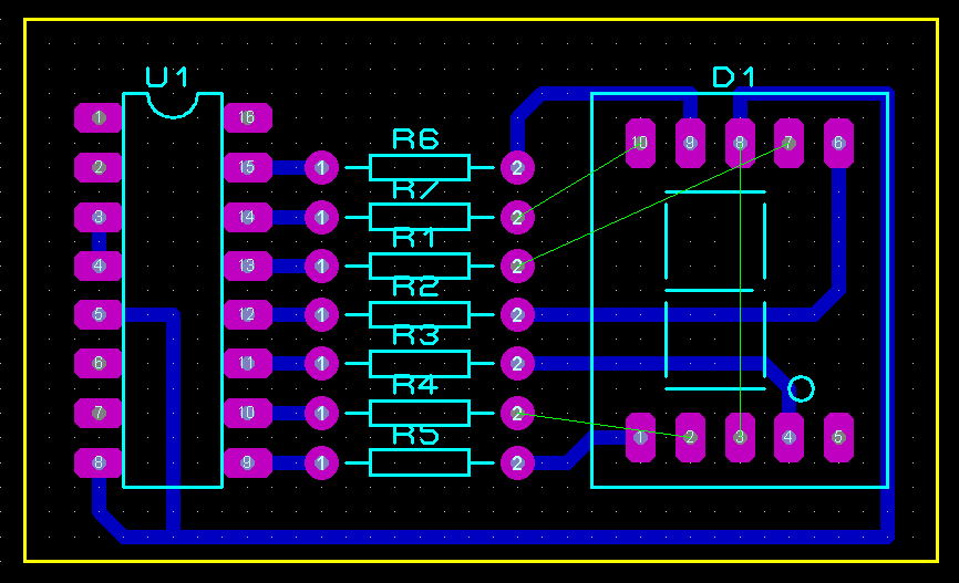
As you can see in previous screenshot, one COM pin is routed and the other COM pin always need to be routed : this method allow connectivity on both pins (normal, as this time, Isis component has two terminals for the two physical COM pins).
Advantages
- In Isis, we can see the component as it will be used in practical usage, with the good pin numbering.- Connectivity checking is possible on all pins.
Disadvantages
- A little less quick, as we have to create an Ares footprint and a new Isis part.Others composants
Creating other components can be done following the same methode. After cretaing of the D350PK display, I immediatly continued with its D350PA "complement" part, that is the Common Anode version.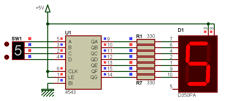
In fact, hardest thing is to start. After encountering some errors (I didn't get what I wanted the first time) and after component is as we want, no reason to stop all...
Test design
You'll find in the following zip archive, an Isis schematic (*.dsn) that make usage of both D350PK and D350PA displays, with the corresponding (and not finished) Ares PCB (*.lyt), as well as 3D model used for 3D view (this model is also in the libraries downloadable on my librairies Proteus page).
Isis / Ares test circuit - 7Seg disp tuto 002.zip